KB 5.2 DIN EN 1993-6KB 4.7 DIN 18800 / DIN 4132DownloadEnquiry

Design of crane runway girders


Efficient structural calculation for crane runway girders - Discover our powerful software solutions.

Our two software solutions KB 4.7a and KB 5.2 can be used to design and provide static verification of crane and trolley girders. The intuitive user interface of our software makes it easy to use.

Crane runway girders KB 5.2 - according to DIN EN 1993-6

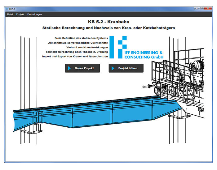
The crane runway girder software KB 5.2 calculates crane runway girders (traveled on the top flange) as well as trolley girders (traveled on the bottom flange). The static system can be freely defined. Single or multi-span beams, optionally also with cantilever arms, can be entered.

Up to three cranes operating at the same time can be arranged on the crane runway. In addition to the warping torsion, the calculation method used also considers the geometrically non-linear behavior of the beam (bending torsion according to second order theory).

Advantages

  • Transparent and easy-to-use input parameters related to the system, the cross section and loads
  • Taking into account various load cases (mass forces of crane and trolley travel, skew, test load, trolley buffer impact and trolley tilting)
  • Free assignment of different cross sections over the entire length of the beam
  • Ability to transfer cross sections and cranes to other projects


Results

  • Proofs at the ultimate limit state (stress, internal force, buckling and resistance of the bottom flange)
  • Proofs at the serviceability limit state (deformations, verification of reversible behavior, limitation of web breathing, vibration of the bottom flange)
  • Proof at fatigue strength limit state
  • If necessary, internal forces and bearing forces are also provided as an output


Crane runway girders KB 4.7a - according to DIN 18800 and DIN 4132

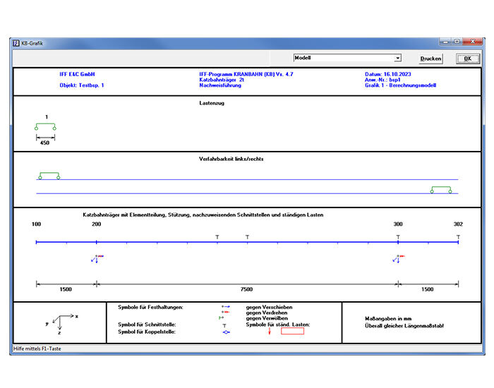
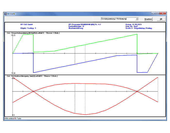
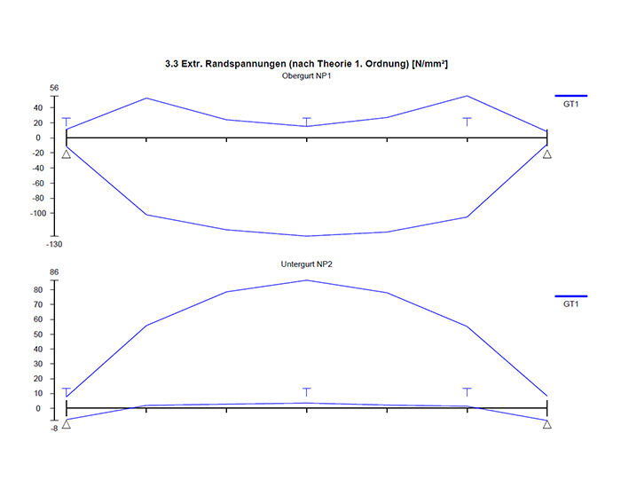
The crane runway girder software KB 4.7a calculates crane runway girders (traveled on the top flange) as well as trolley girders (traveled on the bottom flange). The static system can be freely defined. Single or multi-span beams, optionally also with cantilever arms, can be entered.

Up to three cranes operating at the same time can be arranged on the crane runway. In addition to the warping torsion, the calculation method used also considers the geometrically non-linear behavior of the beam (bending torsion according to second order theory).
Advantages

  • Transparent and easy-to-use input parameters related to the system, the cross section and loads
  • Taking into account various load cases (mass forces of crane travel, skew and tilting of the trolley)
  • Free assignment of different cross sections over the entire length of the beam
  • Automated optimization of the crane runway girder profile


Results

  • Proof of static strength
  • Proof of fatigue strength
  • Proof of buckling strength
  • Proof of deformation and vibration behavior
  • Stability proofs according to second order theory
  • If necessary, internal forces and bearing forces are also provided as an output


Download

KB 5.2 - Crane runway girder according to DIN EN 1993-6

  • Data sheet for KB 5.2

  • Manual for KB 5.2
  • Demo version for KB 5.2


KB 4.7a - Crane runway girder according to DIN 18800/DIN 4132

  • Data sheet for KB 4.7a

  • Manual for KB 4.7a
  • Demo version for KB 4.7a

Enquiry

Are you interested in our software solutions for calculating crane and trolley girders? Then please contact us.

Email: infoiffecde

Phone.: +49 (0)341 4875 2269